
Controls
I mentioned in the last post that my controls from Ultimarc arrived from the U.K. in less than three full days after ordering. Again, impressive! Here are the components unboxed:

This is almost everything that will be needed for the control panel. Twenty-two RGB push buttons, the two 4/8 way switchable joysticks (and the servo motors and control panel for programmatically or electronically switching), trackball, encoder/RGB controller and all the wiring harnesses and connectors that should be needed. The one missing item is the spinner. It was sold out when I placed my order, but a quick email to Andy let me know they'd be back in stock the second week of March. This is the same week I plan on starting the build, but I know from their site that the spinner uses the same size panel hole as the buttons and with the quick shipping turnaround, it shouldn't hold me up any.
There are a number of other components that will also require external cabinet access and will require cutouts or holes in the cabinet.

At the very bottom are two LED lights. I thought it might be nice to embed these in the panel near the joysticks to indicate when the servos/restrictor plates were in motion. The process to switch from 4-way to 8-way (or vice versa) only last a few seconds, but I wanted to see when they were in motion and assure that someone would not be attempting to move the joysticks at the same time. These would have to be flush mounted with the top of the control panel so as not to interfere with the Plexiglass overlay.
At the top of the photo was an item I picked up using a gift certificate around the same time that I was building the prototype, but had not really thought about using it. It's a small RGB LED strip that connects to a control board that takes audio input to control the color and intensity of the lights. Hmmm... wonder would it would look like if I split off the audio from the monitor or amp and ran it to these lights?
I liked it! In addition to what is shown above, the control panel allows for other patterns, but still driven by the source audio. Not completely sure yet where I might mount these. I don't want them shining in the player's face when playing, but since the front lower panel won't go completely to the floor (due to the casters), these could be placed underneath the cabinet to give "ground-effect" lighting. They could also be mounted on the upper back side of the cabinet. This will probably be a game-day decision, as only a small hole would need to be drilled into the cabinet for a couple of lead wires.
Coin Door
When I first unboxed the coin door, I was concerned because it looked like a wire might be broken.

This is the back side of the coin door. About midway up on the right side, you can see the microswitch. If you look closely, you can see a small wire from the switch that feeds into a slot. A quarter drops through the mechanism then across this wire before dropping into the coin collector. The wire in turn, momentarily closes the switch... just like a push button. But when I looked at the other side:

This is the other side of the back, opposite the first photo. The wire circled in yellow is from the switch. But you can see two other springs and I wasn't sure what these did or if either one should be connected to the switch wire. Now, I bought this via Amazon, but the seller was actually X-Arcade. I didn't want to send this back to Amazon if there was nothing wrong with it. I dropped a quick note to X-Arcade support, but wasn't sure if they would assist me since I did not purchase directly from them. But they got right back to me and helped me determine that what I was seeing was correct and by design. Since then, I've been able to hook it up to the Pi and confirm that a quarter is indeed activating the microswitch as designed. This was my second experience with customer service as it should be done (the first, of course, was Ultimarc). As a general rule, I'm trying to remain somewhat vendor neutral here and I'm not looking to commercialize or make money off this blog. But I do always like to recognize outstanding customer service. I will also call out those with abysmal customer service (such a company that rhymes with Bombast). Note that besides cabinet parts like the coin door, X-Arcade has drop-in control panels or even completely built cabinets that just plug in and play... thereby avoiding everything I'm going through in this blog! But here's a shout-out to the customer service folks at X-Arcade:

Internal Components
There are a lot of things I've also obtained that will go inside the cabinet and need to be accounted and planned for:

Here you can see the 5VDC and 12VDC power supplies and terminal strips, a non-powered USB hub, LED lighting for behind the marquee, a couple of scavenged 12VDC cooling fans from an old PC and two power strips. The power strips have USB charging ports so if I end up not being able to spare the Pi USB ports to connect to the external USB ports, I can connect them to the power strip... and in the process, create the worlds largest, most-expensive phone charger!
Graphics
I had also spent some time looking for graphics I would use for the marquee and control panel overlay. I do not have an artistic bone in my body, so designing something on my own and having it printed on vinyl was out of the question. I looked at a number of sites, and decided on Game On Grafix. Yep, naming another vendor.. because, yep, I had questions and these were actually all answered via chat on their site after waiting a whopping 30 seconds or so. I wouldn't be able to even get through the first two voice prompts at "Bombast"... let alone get a real person to assist in that amount of time. They have a massive selection of arcade graphics for marquees, control panels and side panels. Most can be customized with your own text. I debated and debated about what I wanted my marquee to say. I actually had items in my cart a couple of time and emptied it to start again. Since I was going to use blue t-molding on the cabinet, I wanted something in the blue arena. I finally decided and purchased:

Yes... just "ARCADE". I had everything from Man Cave to MAME, but wanted something simple and was afraid that if I tried to put in too many words, the aspect ratio might not look right. Having now received it (about a week or so after ordering), I probably would have selected something along the lines of "Retro Arcade". But I'm designing the marquee so both the Plexiglass and art work could easily be replaced down the road. I can always change it later if I like.
Staying with the blue theme, here is the control panel overlay I ordered:

Both pieces came nicely packed in a sturdy cardboard tube and wrapped with coated paper. They may take a little time to flatten out, but since both will be either sandwiched between sheets of Plexi (marquee) or have a Plexi overlay (control panel), I'm not too worried if they still have a little curl.
Test Mounting
I wanted to take a little time to test hole sizes and mounting options for the Ultimarc and other cabinet controls. I still had some left over 1/2" MDF from the prototype and since both the control panel and vertical admin panel would also be 1/2", this would be perfect. There will be a couple of items, like the "pinball flipper" buttons and the master power switch that will be mounted in the 3/4" side panels, but the hole size would be the same.
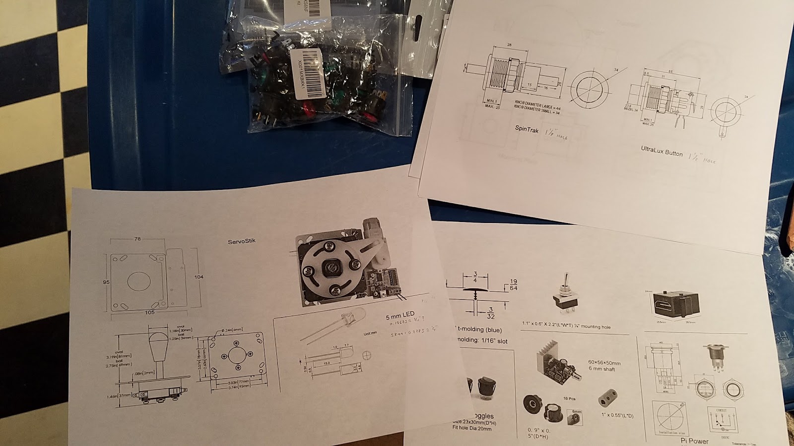
I started out by gathering all the specs from the various parts onto a few pages I could reference and add any specific notes that I discovered. Then I moved on to drilling some initial holes in my test board.

For the USB keystone jacks, I opted to just cut a rectangle hole and use a keystone face plate. I'm not necessarily thrilled with this, but once the panel is painted black it shouldn't be as noticeable and I felt like it was going to be difficult to cut appropriate sizes for the keystone jacks and have it look right. I noted the size of each hole and bit(s) used for each.

Here's the backside. Some of the controls, like the toggle switch and Pi power button are really meant to be mounted on a thin plastic or metal substrate, like a car or boat dash. To allow adequate space to attach lock nuts or retaining rings, it was necessary to use a larger spade bit or router on the back side to narrow the distance.
A side note on routers (this will let you know even more about my limited woodworking experience). I had never used a router before the picture you see above. Ever. I bought a small one at Christmas time just because it was on sale and I knew I was going to eventually need to buy or borrow one to create slots for the t-molding and plexiglass. To be honest, I had to spend some time studying the owner's manual just to figure it out... and was even a little anxious when I first turned it on. But, wow! Where has this tool been all my life? It made it very easy to notch out the area for the toggle switch and now I have a bit more confidence as to how I'm going to build the marquee and display bezels. Now back to our regular programming....

From left to right, are a single color illuminated button from the prototype, the new RGB button that will go in the arcade, the master AC power switch, Pi power button and toggle switch for the joysticks (if needed and I can't get programmatic changes to work). Of course, the face plate for the keystone USB ports is to the far right. Finally, and it's a bit hard to see in the photo, a few inches to the left of the face plate is an embedded 5mm LED light. This will be the indicator to show the joystick is switching the restrictor plate as I talked about above. This was actually the trickiest because there is a very small flange on the bottom of the LED itself and the entire LED is so small, I had to take a lot of care to only drill a small way into the smaller hole with a slightly bigger bit that would allow the flange to fit, but stop just at the right spot so that the top of the LED was flush with the panel. Here's a view from the backside with everything mounted:

There are three additional items to mount that will have to be tested later. One is the trackball. My test pieces were not wide enough to allow me to try to cut those holes. Next are the joysticks. I know the top size hole needed for this, but both the trackball and joysticks use a unique mounting system with brass inserts on the underside that leaves the top of the control panel without any exposed screw heads. It's a nice touch, but impractical to test due to what would be the need for extra brass inserts. The last item is the potentiometer shaft for the amplifier volume. I'm currently awaiting a coupler and shaft extension that should arrive in a couple of days. I don't see an issue with the hole needed in the panel, but it could be tricky to get the amplifier board mounted at just the right position during the build.
Final Checks
So, as a sanity check, I used a nifty little free online tool called SketchUp to completely draw out the cabinet, to scale, in 3D. This allowed me to zoom in/out, rotate the cabinet along 3 axes and assure the depth to width ratio of the cabinet didn't look too out of proportion. Here's an export, but this doesn't do the tool justice:

So, I still need a pal to help me snag the 4'x8' sheets and a few other items, but this completes the planning, testing and design phases. The only thing left to do is build the actual cabinet. The next post will be where the journey truly begins!


Would you be open to providing your Sketchup file? I like your design.
ReplyDeleteI'd be more than happy to... assuming I can find it! I probably created it over four years ago, and when I went to Sketchup, it appears that the original company has been bought out since I last used it... I don't even know what account I used back then. To be honest, I don't know how accurate it would be anyway. I drew everything out to scale by hand and that's what I actually used during the build. If I remember, I threw together the Sketchup file just to try to get an idea of what the dimensions looked like in 3D.
ReplyDeleteBut I'll dig through some of my old files and backups and if I can find the file somewhere, I'll be glad to share it.